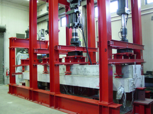
A vertical loading system was constructed at the University of Houston Structural Laboratory that allows testing of full scale girders with 20 ft span and 36 inches in depth. The test frame was specially designed to have a working capacity of 1050 kips. Four MTS hydraulic actuators, A, B, C and D, of 223, 340, 340 and 147-kip capacity, respectively, were used to apply loads on the bent cap. These four loads ensure pure bending between frames B and C, thus guaranteeing an unbiased failure zone.
The actuators were controlled by a versatile FlexTestGT system that allowed load-control as well as strain-control procedures. This system has a Multipurpose Test (MPT) feature that allows the four actuators to work independently or in unison under either a force-control or a displacement-control mode. Moreover, this system offered a unique feature to "hold" (or maintain constant) the forces or the displacements of the actuators.
The test frame in the image shows the horizontal plan view, consisting of two longitudinal beams (anchored to the strong floor) on which are mounted the four vertical frames: A, B, C and D. Each vertical frame is equipped with a corresponding actuator with the same label. Frame A, along with its bottom anchoring beam, was designed to be detachable and movable, thus allowing easy installation and removal of a 20-feet specimen.
Actuators B, C and D are each provided with a swivel base at the top end and one at the bottom end, allowing for any compensation of eccentricities, rotation and movements of the test specimen. Actuator A serves to anchor the test specimen in space and is, therefore, not provided with swivel bases at both ends. The force exerted by each actuator is split equally to the west and east ledges of the test specimen by the P-shaped steel rig. Each of the two legs of the steel rig sits on the ledge through a high-strength steel ball and a bearing plate. Bearing plates of sizes 6 x 6 x 1.25 inch were used for frame A, C & D, while 10 x 6 x 1.25 inch plates were used for frame B. The three actuators, B, C and D, are each equipped with a spherical hinge at the lower end, allowing the P-shaped steel rigs to pivot. In order to prevent the lateral buckling of an actuator at this location, a lateral bracing system is provided, which consists of a pair of channel beams spanning between the two frame columns at the level of the spherical hinge.
